Thermal Spray Coatings
Metallographic Preparation Solutions by Material
Use this guide for advice on where to start when performing metallographic preparation and analysis on thermal spray coatings. Included are tips for achieving the best results for your metallographic application.
Things to consider when working with Thermal Spray Coating (TSC)

Components of the substrate and coating as well as the manufacturing process can differ. These differences can change the products used for sample preparation (blades, grinding, polishing, mounting method, etc.).
With coatings often being the focus for analysis, it is important that internal structures are retained. Porosity, thickness, and adherence to the substrate are commonly examined. To preserve these characteristics samples are often mounted using epoxy systems prior to other preparation methods. Low-viscosity, castable systems are recommended with vacuum systems to mount the specimen.
Thermal Spray Coating Cutting Tips


Precision saws induce less damage in coatings than abrasive saws. When sectioning a thermal spray coating there are a few things to consider:
- Composition
- Orientation/Support
- Structure
To select a blade, it is important to know the material that makes up the sample. The blade used should be suitable for material that is more difficult to cut. IsoCut® wafering blades are commonly employed, as coatings are sometimes deposited on nickel alloys or steel substrates. Series 15 HC precision blades may be used on metallic coatings such as titanium. Sectioning time and blade life are influenced by blade choice.
The orientation of thermal spray coating when sectioning is important. Due to the ability of the coatings to delaminate or fracture, samples should be cut under compression. Ensure the blade is entering the coating and exiting through the substrate. The use of a Double Saddle Chuck supports both sides of the cut which can improve cut quality. When clamping it’s good practice to pad the chuck with a softer material. This can be done with small strips of polishing cloth adhered to the chucks clamping surface and ensures the ability to clamp firmly without damaging the coating.
If the sample is porous, friable, or has multiple sides coated, mounting the sample before sectioning would help support the internal structures.
Thermal Spray Coating Mounting Tips
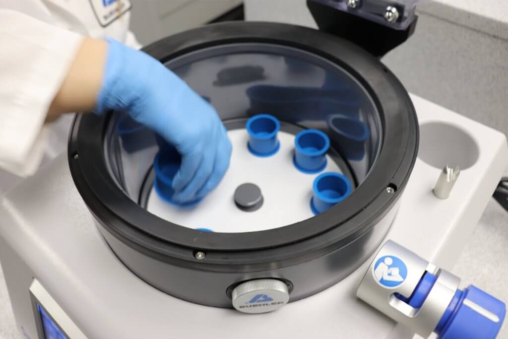
A low-viscosity epoxy system can fill gaps in the coating, helping to hold the internal structures. EpoThin® is recommended for optimal edge retention and infiltration though this requires a nine hour cure time. If shorter times are required then EpoKwick® FC is a good alternative by reducing the cure time to two hours. Cycling samples multiple times under vacuum greatly improves pore impregnation, optimizes sample adherence, and provides additional support for delicate thermal spray samples. The SimpliVac allows a user to pour under vacuum and automate the cycling process. We suggest using 25 inHg and going through 10 cycles of 60 seconds as demonstrated in Improve Sample Quality by Running Multiple Cycles with SimpliVac Article. Adding a dye to the epoxy will help distinguish between the sample and the pores.
While there are always exceptions, hot compression mounting is generally not recommended for thermal spray coatings because high-pressure levels can cause damage to the coating’s internal structure.
Thermal Spray Coating Grinding & Polishing Tips for All Methods

Central force is recommended when preparing TSCs. Central force specimen holders secure the sample in place within the holder for all grinding and polishing steps. Samples should be prepared under compression to reduce the chances of damaging the coating. To keep samples in compression orient coatings so abrasives cut through the coating first and then exit through the substrate. During polishing, the coating should push against and be supported by the substrate to reduce potential damage. Force is applied to the center and dispersed amongst the sample faces.
Thoroughly clean samples between preparation steps. Porous samples are likely to pick up particles. Minimize contamination by putting samples in an ultrasonic bath between steps.
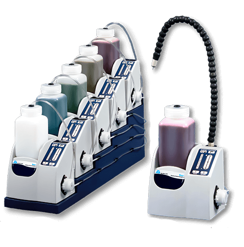
Using Buehler’s Burst dispensing system can conserve diamonds and improve consistency.
The ideal rate for the Burst dispensing system changes with the size of the platen and the polishing cloth that is being used. As a general guideline, for a platen size of 8” a burst setting of 3 is a good starting point, for sizes of 10″ and 12″ set the burst system to 4 and adjust as needed. Some experimentation may be required to determine optimal settings to ensure sufficient abrasive and wetting of the cloth. Burst dispensers are also capable of dispensing extenders simultaneously with diamond if desired.
Loads listed in grinding and polishing methods are recommendations for one 1.25″ mounted specimen. If using central force during preparation the force listed should be multiplied by the number of samples being polished. For different sample sizes, use our load conversion calculator to determine the correct load for your application
| 4-Step Method for Ceramic Thermal Spray Coatings | ||||
|---|---|---|---|---|
| Surface | Load lbs [N] | Base Speed [rpm] | Relative Rotation | Time |
| DGD Ultra (45-μm Diamond) | 5 [22] | 300 rpm |
| Until Plane |
| UltraPad with 9um MetaDi Supreme Diamond | 5 [22] | 200 rpm |
| 6:00 |
| TriDent with 3um MetaDi Supreme Diamond | 6 [27] | 120 rpm |
| 5:00 |
| ChemoMet with MasterMet Colloidal Silica | 6 [27] | 120 rpm |
| 2:00 |
|
| ||||
| 4-Step Method for Metallic Thermal Spray Coatings | ||||
|---|---|---|---|---|
| Surface | Load lbs [N] | Base Speed [rpm] | Relative Rotation | Time |
| DGD Color Yellow (35-μm Diamond) | 6 [27] | 300 rpm |
| Until Plane |
| UltraPad with 9um MetaDi® Supreme Diamond | 6 [27] | 150 rpm |
| 4:00 |
| TriDent with 3um MetaDi Supreme Diamond | 6 [27] | 150 rpm |
| 3:00 |
| ChemoMet® with MasterMet® Colloidal Silica | 4 [18] | 150 rpm |
| 2:00 |
|
| ||||
Thermal Spray Coating Etching Tips
Thermal Spray Coating Imaging Tips

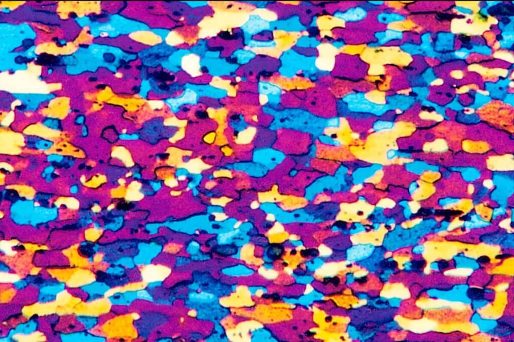
Common coatings analysis includes measurement of porosity, coating thickness, and defects in adhesion. All can be measured using our OmniMet® software Advanced. Measurements, annotations, and percentage analysis can be determined for designated sample areas.
Thermal Spray Coating Hardness Testing Tips
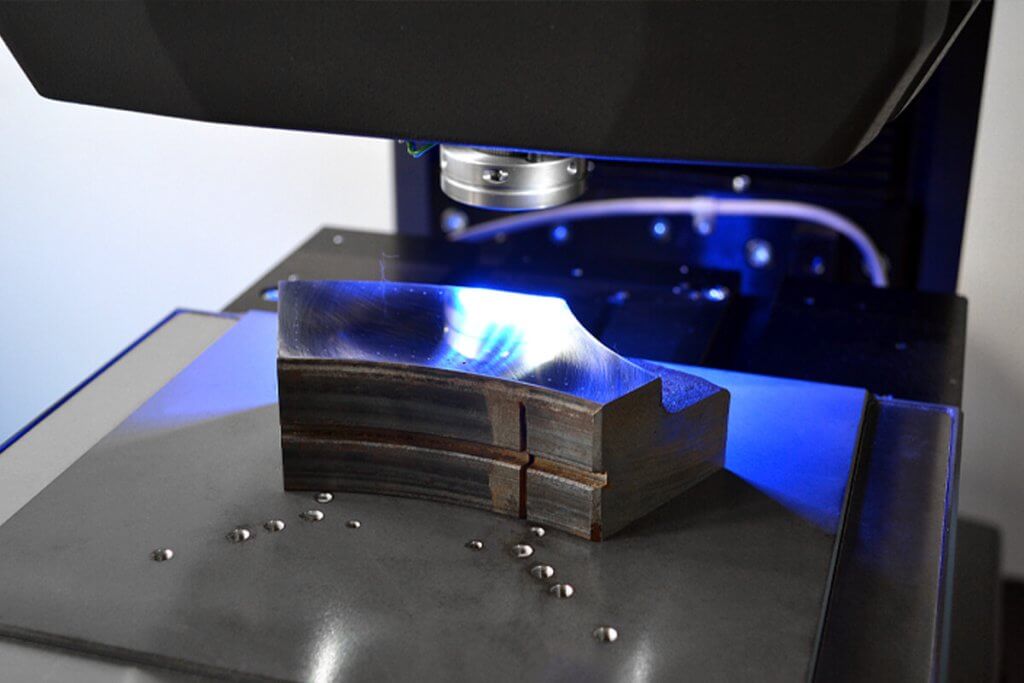
When the method of hardness testing is being decided on, the application is assessed to find the scale that fits the needs outlined. At Buehler, our equipment supports hardness testing using four scales: Brinell, Rockwell, Vickers, and Knoop. Depending on the sample and information required the scale needed can change.
While working with spray coatings several factors could affect the ability to measure the indent.
The surface finish of the specimen; flatness and scratches would hinder software auto-measuring indents. To reduce uneven surface finish, ensure that the samples are smooth before starting the polishing process.
Coating geometries do not always allow for easy hardness testing. Selection of test area can be difficult because of pores and limited area to indent. When testing, if an indent lays over a pore, it could lead to an abnormally shaped indent and require re-testing in another location. Using Epoxy to support the coating structure can help reduce the likelihood of this happening.
Indent tips may be hidden or obscured within pores and cracks. Ceramic coatings are especially susceptible to this. One way to abate these effects when indenting on a thermal spray coating is to use a lighter load. Lighter loads not only decrease the chances of cracking but also allow for the targeting of solid areas of coating material. Configure equipment with a 100x objective when measuring indents 20 microns or smaller.
Good contrast is important with indent measurements when analyzing samples comprised of an undercoat and overcoat having different levels of reflectance. Adjust the lighting for each coating. DiaMet Full-automatic and up have settings to allow automated illumination, and focus.

Related Products
All Solutions by Material
Choose a material to view Buehler's resources

Find Your Solutions
Full Lab
Metallography Solutions
Do you want to improve your process? Reach out for one-on-one help from our applications experts.

View all Products in the Buehler Product Catalog

Select a method by material

Search Buehler's Safety Data Sheets

Browse and search Buehler's product literature
 Europe | EN


