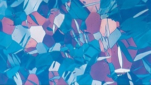
 Metallographic etching encompasses all processes used to reveal particular structural characteristics of a metal that are not evident in the as-polished condition. Examination of a properly polished specimen before etching may reveal structural aspects such as porosity, cracks, and nonmetallic inclusions.
Indeed, certain constituents are best measured by image analysis without etching, because etching will reveal additional, unwanted detail and make detection difficult or impossible. The classic examples are the measurement of inclusions in steels and graphite in cast iron. Of course, inclusions are present in all metals, not just steels. Many intermetallic precipitates and nitrides can be measured effectively in the as-polished condition.
In certain nonferrous alloys that have non-cubic crystallographic structures (such as beryllium, hafnium, magnesium, titanium, uranium and zirconium), grain size can be revealed adequately in the as polished condition using polarized light. Figure 20.1 shows the microstructure of cold-drawn zirconium viewed in cross-polarized light. This produces grain coloration, rather than a “flat etched” appearance where only the grain boundaries are dark.
Metallographic Etching Procedures
 Microscopic examination is usually limited to a maximum magnification of 1000X — the approximate useful limit of the light microscope, unless oil immersion objectives are used. Many image analysis systems use relay lenses that yield higher screen magnifications that may make detection of fine structures easier. However, resolution is not improved beyond the limit of 0.2-0.3µm for the light microscope.
Microscopic examination of a properly prepared specimen will clearly reveal structural characteristics such as grain size, segregation, and the shape, size, and distribution of the phases and inclusions that are present. Examination of the microstructure will reveal prior mechanical and thermal treatments give the metal. Many of these microstructural features are measured either according to established image analysis procedures, e.g., ASTM standards, or internally developed methods.
Metallographic etching is done by immersion or by swabbing (or electrolytically) with a suitable chemical solution that essentially produces selective corrosion. Swabbing is preferred for those metals and alloys that form a tenacious oxide surface layer with atmospheric exposure such as stainless steels, aluminum, nickel, niobium, and titanium and their alloys. It is best to use surgical grade cotton that will not scratch the polished surface. Etch time varies with etch strength and can only be determined by experience. In general, for high magnification examination the etch depth should be shallow; while for low magnification examination a deeper etch yields better image contrast. Some etchants produce selective results in that only one phase will be attacked or colored.
Selective Etching
 Image analysis work is facilitated if the etchant chosen improves the contrast between the feature of interest and everything else. Thousands of etchants have been developed over the years, but only a small number of these are selective in nature. Although the selection of the best etchant, and its proper use, is a very critical phase of the image analysis process, only a few publications have addressed this problem.
A classic example of the different behavior of etchants is given in Figure 20.2 where low-carbon sheet steel has been etched with the standard nital and picral etchants, and also a color tint etch.
Etching with 2% nital reveals the ferrite grain boundaries and cementite. Note that many of the ferrite grain boundaries are missing or quite faint; a problem that degrades the accuracy of grain size ratings. Etching with 4% picral reveals the cementite aggregates (one could not call this pearlite as it is too nonlamellar in appearance and some of the cementite exists as simple grain boundary films) but no ferrite grain boundaries. If one is interested in the amount and nature of the cementite (which can influence formability), then the picral etch is far superior to the nital etch as picral revealed only the cementite.
Tint etching with Beraha’s solution (Klemm’s I could also be used) colored the grains according to their crystallographic orientation. With the development of color image analyzers, this image can now be used quite effectively to provide accurate grain size measurements since all of the grains are colored.
Figure 20.3 shows a somewhat more complex example of selective etching. The micrograph shows the ferrite-cementite-iron phosphide ternary eutectic in gray iron.
Etching sequentially with picral and nital revealed the eutectic, Figure20.3a, surrounded by pearlite. Etching with boiling alkaline sodium picrate, Figure 20.3b, colored the cementite phase only, including in the surrounding pearlite (a higher magnification is required to see the very finely spaced cementite that is more lightly colored). Etching with boiling Murakami’s reagent, Figure 20.3c, colors the iron phosphide darkly and will lightly color the cementite after prolonged etching. The ferrite could be colored preferentially if Klemm’s I was used.
Selective etching has been commonly applied to stainless steels for detection, identification and measurement of delta ferrite, ferrite in dual phase grades, and sigma phase.
Figure 20.4 shows examples of the use of a number of popular etchants to reveal the microstructure of a dual phase stainless steel in the hot rolled and annealed condition.
Figure 20.4a shows a well delineated structure when the specimen was immersed in ethanolic 15% HCl for 30 minutes. All of the phase boundaries are clearly revealed, but there is no discrimination between ferrite and austenite. Twin boundaries in the austenite are not revealed. Glyceregia, a etchant for stainless steels, was not suitable for this grade, Figure 20.4b, as it appears to be rather orientation sensitive.
Many electrolytic etchants have been used for etching stainless steels, but only a few have selective characteristics. Of the four shown in Figures 20.4c to f, only aqueous 60% nitric acid produced any gray level discrimination between the phases, and that was weak.
All revealed the phase boundaries nicely, however. Two electrolytic reagents, shown in Figures 20.4g and h, are commonly used to color ferrite in dual phase grades and delta ferrite in martensitic grades.
Of these, aqueous 20% sodium hydroxide, Figure 20.4g, usually gives more uniform coloring of the ferrite. Murakami’s and Groesbeck’s reagents have also been used for this purpose. Tint etchants have been developed by Beraha that color the ferrite phase nicely, as demonstrated in Figure 20.4i.
Selective etching techniques are not limited to iron based alloys, although these have more thoroughly developed than for any other alloy system. Selective etching of beta phase in alpha-beta copper alloys has been a popular subject.
Selective etching has a long historical record for identification of intermetallic phases in aluminum alloys. This method was used for many years before the development of energy-dispersive spectroscopy. Today, it is still useful for image analysis work.
Figure 20.5 illustrates the structure of a simple WC-Co sintered carbide, cutting tool. In the as-polished condition, Figure 20.5a, the cobalt binder can be seen faintly against the more grayish tungsten carbide grains. A few particles of graphite are visible.
In Figure 20.5b, light relief polishing has brought out the outlines of the cobalt binder phase, but this image is not particularly useful for image analysis. Etching in a solution of hydrochloric acid saturated with ferric chloride, Figure 20.5c, attacks the cobalt and pro- vides good uniform contrast for measurement of the cobalt binder phase.
Following this with Murakami’s reagent at room temperature reveals the edges of the tungsten carbide grains, useful for evaluation of the WC grain size, Figure 20.5d.
Heat Tinting
 Although not commonly utilized, heat tinting is an excellent method for obtaining color contrast between constituents or grains. An unmounted polished specimen is placed face up in an air-fired furnace at a set temperature and held there as an oxide film grows on the surface.
Interference effects, as in tint etching, create coloration for film thicknesses within a certain range, about 30-500nm. The observed color is a function of the function of the film thickness. Naturally, the thermal exposure cannot alter the microstructure. The correct temperature must be determined by the trial-and-error approach, but the procedure is reproducible and reliable.
Interference Layer Method
The interference layer method, introduced by Pepperhoff in 1960, is another procedure for obtaining a film over the microstructure that generates color by interference effects. In this method, a suitable material is deposited on the polished specimen face by vapor deposition to produce a low-absorption, dielectric film with a high refractive index at a thickness within the range for interference.
Very small differences in the natural reflectivity between constituents and the matrix can be dramatically enhanced by this method. The technique is universally applicable, but does require a vacuum evaporator. Its main weakness is difficulty in obtaining a uniformly coated large surface area for image analysis measurements.
Helpful Hints for Etching
Many etchants can be used by swabbing or by immersion. Swabbing is preferred for those specimens that form a tight protective oxide on the surface in air, such as Al, Ni, Cr, stainless steels, Nb (Cb), Ti and Zr. However, if the etchant forms a film, as in tint etchants, then immersion must be used as swabbing will keep the film from forming. Keller’s reagent reveals the grain size of certain aluminum alloys by forming a film. This will not occur if the etch is used by swabbing.
Many etchants, and their ingredients, do present potential health hazards to the user. ASTM E 2014, Standard Guide on Metallography Laboratory Safety, describes many of the common problems and how to avoid them.
 Europe | EN





2 Responses
why does Gas Nitride layer on stainless steels like PH17-4 darkens with almost any reagents for this type of alloys, Nital, Marble’s, Fry’s Kaling’s even Oxalic reagents?
Why Carburized etches lighter than Nitride layer?
Hi Miguel – thank you for your question!
The etching process is designed to be a selective reaction to specifically highlight different features. This can be done through differences in crystal structure, or chemistry. As carburized and nitrided areas have different chemistry, they react differently. We have a wide variety of etchants to select from, and sometimes use different etches in order to create different contrast – please contact us at lab.us@buehler.com if you have a need to etch in specific ways and we can advise further!